Difference between revisions of "Denavit-Hartenberg parameters"
| Line 85: | Line 85: | ||
Considerable aspects of this manipulator are: | Considerable aspects of this manipulator are: | ||
| − | * | + | * <math>d_n=-k_2</math> as the translation is applied in negative direction along the <math>x_1</math>-axis. |
| + | * <math>d_3=k_4</math> is the only dynamic offset along the <math>z_{2}</math>-axis as the corresponding joint <math>J_3</math> is a prismatic joint. Like explained above, the whole offset along <math>z_{n-1}</math>, here indicated with <math>k_4</math>, is used as <math>d_n</math>-parameter in case of a prismatic joint. | ||
| + | * At the coordinate frame <math>K_4</math>, the <math>x</math>-axis changes its direction and is no longer collinear with the previous one. A rotation by <math>-90^\circ</math> about <math>z_3</math> is necessary to align <math>x_4</math> with <math>x_3</math>. As joint <math>J_4</math> is a revolute joint with joint parameter <math>\psi_4</math>, the corresponding parameter results in <math>\theta_4=-90^\circ+\psi_4</math>. | ||
| + | |||
<table style="background-color: #444444"> | <table style="background-color: #444444"> | ||
Revision as of 18:17, 16 November 2015
| ← Back: Assigning coordinate frames | Overview: Denavit-Hartenberg Convention | Next: A-matrices → |

When the coordinate frames are assigned to a manipulator, the transformation between each two consecutive frames has to be described. As before for the assignment of the coordinate frames, the manipulator has to be in its zero position as well for the determination of the parameters. The figure on the right shows the two coordinate frames  and
and  in their zero position and the corresponding common normal represented by a dashed red line. To describe the transformation of with respect to , the 4 Denavit-Hartenberg parameters
  ,
,  ,
,  and
and  are used. These parameters describe the static transformation within link
  , but as well include the dynamic influence of the joint parameter of
  , that could change over time. The figure illustrates the parameters, that are defined as follows:
|
|
The angle

| ||||
|
|

| ||||
|
|
The parameter If the related joint | ||||
|
|
The angle |
 -axis.
 ) has to be included in the Denavit-Hartenberg parameter
  at the distal joint. The coordinate frames are shown in their zero position. The angle
  describes the rotation about the
  -axes.
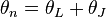

 is based on the geometric structure of the link and also valid in the zero position. The dynamic offset
  corresponds to the joint parameter and so to the displacement of joint
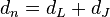
 . So no distinction between the static and the dynamic part is made for reasons of simplification:
  .
.
 -axis
-axis
- Placement in the context of transformations
- The 4 parameters can rather be determined by just regarding the two coordinate frames, their axes and the common normal like visualized above. To completely understand the parameters and their meaning, the figure below illustrates what the parameters actually describe.
 ,
,  ,
,  and
and  define 4 transformations that are applied consecutively to transform the coordinate frame to . First a rotation about the
  -axis by is applied followed by a translation along it by . Then the coordinate frame is rotated about the
  -axis by . Finally a translation along the -axis leads to the next coordinate frame . Some further aspects about the meaning and the use of the 4 parameters are described in the following article about the A-matrices.

The video at the end of this page explains the assignment of the coordinate frames and the determination of the 4 parameters very vividly and comprehensibly.
|


 The table below contains the Denavit-Hartenberg parameters for the manipulator shown in the figure on the right. For further information about the already assigned coordinate frames, have a look on the examples of the previous articles. The necessary lengths of certain parts of the manipulator are indicated by the variables Considerable aspects of this manipulator are:
|
 to
to  .
.
 as the translation is applied in negative direction along the
  -axis.
 is the only dynamic offset along the
  -axis as the corresponding joint
  is a prismatic joint. Like explained above, the whole offset along
  , is used as
  , the
, the  about
about  is necessary to align
  with
with  . As joint
  is a revolute joint with joint parameter
  , the corresponding parameter results in
 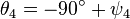 .
.


Multimedial educational material
|
|
https://www.youtube.com/watch?v=qZB3_gKBwf8 Video: Assignment of coordinate frames and determination of the parameters (in German) |
