Difference between revisions of "Common normal"
| Line 13: | Line 13: | ||
# When the lines through the two joint axes ''intersect'', their distance and so the length of the common normal is <math>0</math>. But the imaginary direction that the common normal would have is distinct and it would start (and end as it has length <math>0</math>) in the intersection point. | # When the lines through the two joint axes ''intersect'', their distance and so the length of the common normal is <math>0</math>. But the imaginary direction that the common normal would have is distinct and it would start (and end as it has length <math>0</math>) in the intersection point. | ||
# When the joint axes are ''collinear'', their distance or the length of the common normal, respectively, is <math>0</math>. The imaginary direction of the common is orthogonal to the joint axes. But as both lines are collinear it could be rotated by any angle about the line. Additionally its position along the line is not distinct. | # When the joint axes are ''collinear'', their distance or the length of the common normal, respectively, is <math>0</math>. The imaginary direction of the common is orthogonal to the joint axes. But as both lines are collinear it could be rotated by any angle about the line. Additionally its position along the line is not distinct. | ||
| + | |||
{{Example | {{Example | ||
| Line 18: | Line 19: | ||
|Contents= | |Contents= | ||
| − | The left side of the figure below shows a manipulator in its zero position | + | The left side of the figure below shows a manipulator in its zero position with already assigned [[Types of joints<main joint axes]]. |
| − | |||
| − | |||
| − | The | + | The [[Common normal|common normals]] have to be computed based on each two consecutive main joint axes. The main axis of <math>J_1</math> is pointing upwards and the one of <math>J_2</math> to the right. As <math>J_2</math> is translated along the negative <math>x_0</math>-axis into the figure, the two lines are non-intersecting. This is the general case of the [[Common normal|common normal]]. So the shortest line perpendicular to both lines is pointing into the figure at the height of <math>J_2</math>. This is shown as a dashed red line. The red dot at the end of it indicates the intersection of the common normal with the main joint axis of the distal joint, which is defined as the origin of the next coordinate frame. For <math>J_2</math> and <math>J_3</math> we have the [[Common normal|''parallel'' case]]. |
| − | [[File:dh-ex- | + | [[File:dh-ex-comnorm.png|center|950px]] |
}} | }} | ||
Revision as of 11:25, 11 November 2015
| ← Back: Notation of links, joints and coordinate frames | Overview: Denavit-Hartenberg Convention | Next: Assigning coordinate frames → |
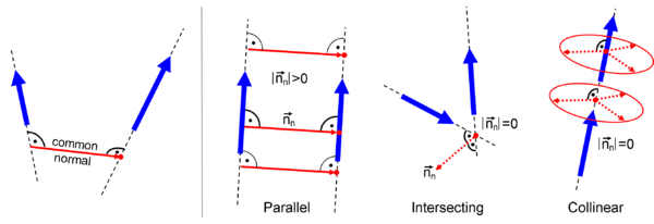
The common normal is the shortest line perpendicular to the main joint axes of two consecutive joints. So it corresponds to the distance of two lines through the joints with the joint axes as direction vectors. This is illustrated on the left side of the figure on the right. The direction of the common normal can be computed using the cross product of the two main joint axes, so of the two  -axes:
Its length depends on the spatial relation of the joint axes. There are some special cases, shown on the right side of the figure, that have to be considered when assigning the coordinate frames.
- Special cases
- When the two joint axes are parallel or antiparallel, the length of the common normal is distinct and larger than zero. But the position along the two axes is not distinct as two parallel lines have the same distance all over.
- When the lines through the two joint axes intersect, their distance and so the length of the common normal is
 . But the imaginary direction that the common normal would have is distinct and it would start (and end as it has length
  ) in the intersection point.
 - When the joint axes are collinear, their distance or the length of the common normal, respectively, is
 . The imaginary direction of the common is orthogonal to the joint axes. But as both lines are collinear it could be rotated by any angle about the line. Additionally its position along the line is not distinct.
The left side of the figure below shows a manipulator in its zero position with already assigned [[Types of joints<main joint axes]]. The common normals have to be computed based on each two consecutive main joint axes. The main axis of |


 is pointing upwards and the one of
  to the right. As
  -axis into the figure, the two lines are non-intersecting. This is the general case of the common normal. So the shortest line perpendicular to both lines is pointing into the figure at the height of
  we have the parallel case.
