Assigning coordinate frames
| ← Back: Denavit-Hartenberg Convention | Overview: Denavit-Hartenberg Convention | Next: Denavit-Hartenberg parameters → |
To be able to determine the spatial relationship or transformation, respectively, between the links of a manipulator, local coordinate frames have to be assigned to them first. There are several rules that have to be observed when assigning coordinate frames following the Denavit-Hartenberg convention. The first rule is, that the manipulator has to be moved to its zero position. So all the joints or their joint parameters, respectively, have to be set to zero. Then the coordinate frames are assigned regarding the zero position.
Notation
The notation of the links and joints is shown in the figure below. A manipulator consists of  links that are connected with
  joints. The links correspond to the rigid parts of an arm and the joints are the flexible connections between them. A joint is always assigned to the proximate link. So a link
  is connected with its joint
  to the end of link
  . The proximate link
  is then mounted to the end of
  via its joint
  . The first link
  is mounted on the base via joint
  . So the base is actually link
  but does not directly belong to the manipulator. The end of the last link
  corresponds to the end-effector.
The coordinate frames are always attached to the end of the links at the distal joints. The first coordinate frame, indexed  , is the base or reference frame and attached to the base in joint
  . The next frame is
  at the end of link
  in joint
  followed by
  at the end of
  and so on. The coordinate frame
  of the last link is finally attached to the end of of the manipulator and so to the end-effector.
Main joint axes
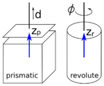
Following the above notation, a coordinate frame is attached to each end of a link at the corresponding joint. The orientation of the coordinate frames depends on the joint and on the prior frame. There is one rule, that is always valid. This is, that the  -axis of a coordinate frame is always pointing in the direction of the main axis of the related joint. Like can be seen in the figure on the left, the main axis of a prismatic joint is the axis along which the displacement in positive direction is applied. For a revolute joint, the main axis is the rotation axis. The direction of the rotation axis and so of the main axis is depending on the positive rotation direction. When you hold your right hand like shown on the right and point your thumb in the direction of the rotation axis, the four other fingers indicate the rotation direction for positive angles. So the right hand can be used to determine the direction of the main axis. In the figure on the left, the thumb of the right hand has to point upwards, so that the four fingers correspond to the direction of the arrow indicating the positive rotation direction. Thus the main axis is directed upwards as well.
Common normal
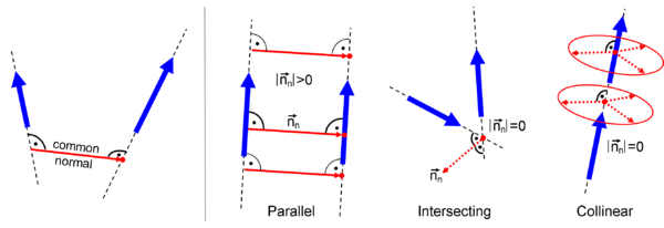
The common normal is the shortest line perpendicular to the joint axes of two consecutive joints. So it corresponds to the distance of two lines through the joints with the joint axes as direction vectors. This is illustrated on the left side of the figure on the right. The direction of the common normal can be computed using the cross product of the two main joint axes, so of the two  -axes:
Its length depends on the spatial relation of the joint axes. There are some special cases, shown on the right side of the figure, that have to be considered when assigning the coordinate frames:
- When the two joint axes are parallel or antiparallel, the length of the common normal is distinct and larger than zero. But the position along the two axes is not distinct as two parallel lines have the same distance all over.
- When the lines through the two joint axes intersect, their distance and so the length of the common normal is
 . But the direction that the common normal would have is distinct and it would start (and end as it has length
  ) in the intersection point.
 - When the joint axes are collinear, their distance or the length of the common normal, respectively, is
 . The direction of the common is orthogonal to the joint axes. But as both lines are collinear it could be rotated by any angle about the line. Additionally its position along the line is not distinct.
Assigning the coordinate frames
Following the notation presented above, the first coordinate frame is always the base or reference frame  . The origin of the base is coincident with the origin of the first joint and their axes are aligned. So the joint axis of the first frame is always normal to the
  -plane of the base or world frame, respectively. As the world frame is usually known, the orientation of
  is already defined and does not have to be determined.
|


