Types of joints
| ← Back: Denavit-Hartenberg Convention | Overview: Denavit-Hartenberg Convention | Next: Notation of links, joints and coordinate frames → |
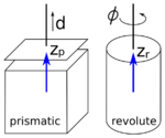
There are two types of joints used for robotic arms, each with one single degree of freedom. In the following the abstractions shown in the figure on the left will be used. The first type is the prismatic joint, that allows for translational movement along the joint axis. The displacement is described by the joint variable, for example  like in the figure. The second joint type is the revolute joint. A revolute joint allows for a rotation about the joint or rotation axis, respectively, and its joint parameter is the rotation angle, named
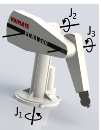
  in the figure. The Puma560 for example has three revolute joints (see figure on the right).
Following the above notation, a coordinate frame is attached to each end of a link at the corresponding joint. The orientation of the coordinate frames depends on the joint and on the prior frame. There is one rule, that is always valid. This is, that the  -axis of a coordinate frame is always pointing in the direction of the main axis of the related joint. Like can be seen in the figure on the left, the main axis of a prismatic joint is the axis along which the displacement in positive direction is applied. For a revolute joint, the main axis is the rotation axis. The direction of the rotation axis and so of the main axis is depending on the positive rotation direction. When you hold your right hand like shown on the right and point your thumb in the direction of the rotation axis, the four other fingers indicate the rotation direction for positive angles. So the right hand can be used to determine the direction of the main axis. In the figure on the left, the thumb of the right hand has to point upwards, so that the four fingers correspond to the direction of the arrow indicating the positive rotation direction. Thus the main axis is directed upwards as well.
three joints  ,
,  and
and  , the end-effector of the Puma560,
The end-effector of the Puma560, which is the black part at the end of the arm, is located at different positions and with a different orientation.


