Roll-Pitch-Yaw
| ← Back: Three-Angle Representations | Overview: Three-Angle Representations | Next: Euler angles → |

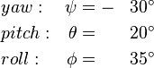
The roll, pitch and yaw angles are three angles defined in regard of absolute transformation to describe the orientation of an object, generally vehicles, in three-dimensional space. In the following the common convention will be used, so the three angles can be described as follows (in the order they are applied):
- Yaw: Rotation around the vertical axis of the object or vehicle, respectively
- Pitch: Rotation around the lateral axis
- Roll: Rotation around the longitudinal axis (what is generally the movement axis of a vehicle)
There are different notations to define the axes of an object. Usually and in recent publications the vertical axis is the z-axis, the longitudal axis is x and then the lateral axis is the y-axis and directed to the left.
So the roll-pitch-yaw transformation matrix of the orientation is defined as follows:
![\begin{align}
RPY(\phi,\theta,\psi)&=Rot(x,\phi)Rot(y,\theta)Rot(z,\psi) \\
&=
\left[\begin{array}{cccc}
\cos{\psi}\cos{\theta} & -\cos{\theta}\sin{\phi} & \sin{\theta} & 0\\
\cos{\psi}\sin{\phi}+\cos{\phi}\sin{\psi}\sin{\theta} & \cos{\phi}\cos{\psi}-\sin{\phi}\sin{\psi}\sin{\theta} & -\cos{\theta}\sin{\psi} & 0\\
\sin{\phi}\sin{\psi}-\cos{\phi}\cos{\psi}\sin{\theta} & \cos{\phi}\sin{\psi}+\cos{\psi}\sin{\phi}\sin{\theta} & \cos{\psi}\cos{\theta} & 0\\
0 & 0 & 0 & 1
\end{array}\right]
\end{align}](/wiki/robotics/images/math/9/9/e/99e76f6d0ec3707b9a143fd83b9ad825.png)
Then the rotation matrix then results as: The figure below shows how the three transformations are applied step by step. First the car is rotated around the z-axis about the yaw angle. Then the rotation around the y-axis follows and finally the car is rotated around the x-axis. The final orientation can be seen in the last view.
If the matrix and the final orientation of the car are compared, it can be seen, that the vectors |
![\begin{align}
RPY(35^\circ,20^\circ,-30^\circ)&=Rot(x,35^\circ)Rot(y,20^\circ)Rot(z,-30^\circ) \\
&=
\left[\begin{array}{cccc}
0.8138 & 0.4698 & 0.3420 & 0\\
-0.2397 & 0.8075 & -0.5390 & 0\\
-0.5294 & 0.3566 & 0.7698 & 0\\
0 & 0 & 0 & 1
\end{array}\right] \\
&=
\left[\begin{array}{cccc}
\vec{\mathbf{x}} & \vec{\mathbf{y}} & \vec{\mathbf{z}} & \vec{\mathbf{p}}\\
0 & 0 & 0 & 1 \\
\end{array}\right]
\end{align}](/wiki/robotics/images/math/c/b/2/cb221b0855a9dda983fd613b0915dd87.png)

 and
and  correspond to the three local coordinate axes of the car. Position vector
  is a zero vector in this case.